

Small Mechanical Strength Testing Machine - CT6
Testing range - 0.02 to 500 kg (0.2 to 5000N)
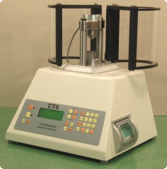
The CT6 is for testing small objects in compression or in 3 or 4 point bending,
within the above load limits. The maximum specimen size lies within a 50 mm cube.
The machine is self contained with its own keyboard & printer, and has input connectors
for a weigh balance and thickness calliper. This enables the strength, weight and
thickness of a specimen to be incorporated into the results output, which can
also include statistical data. Results are printed on the internal printer
or transferred to a PC via the USB or RS232 interface.
The machine also has a graph plotting routine and during a test, a plot of load
vs. distance can be shown on a PC via the USB output.
Also incorporated is an input for an acoustic sensor. This can be used for
fracture and crack detection, the sensitivity can be varied to suit the test.
The amplified acoustic signal is accessible via a BNC connector.
The CT6 is small enough to be moved or carried by one person, it weighs 15 kg.
![]() Click here to download a PDF brochure.
Click here to download a PDF brochure.
Further Details
- Test speed range: 0.1 - 50 mm/min. (Fast up and down speed ~ 50 mm/min)
- A choice of load cells is available: 5 kg, 10 kg, 50 kg and 500 kg maximum load. Note that each load cell has a resolution of 1:5000 and a minimum fracture detect level of ~ 0.5% of its rated maximum load, i.e. a 50 kg cell would have a resolution of 0.01 kg and a minimum fracture detect of ~ 0.25 kg.
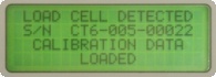
- Load cell ID: This feature recognises pre-calibrated load cells (on any individual CT6) and automatically sets the correct calibration factor when a load cell has been changed.
- Choice of units: kg, N and lb. Also kp, although this is not recommended.
- LCD display shows: Load, speed, position, test count, weight & thickness if relevant. Time - if required, etc.
- Statistical analysis: Max, Min, Mean & Standard deviation, Time & Date. For Load and Weight + Thickness if relevant.
- Maximum mechanical travel: 50 mm. Pillar extensions give maximum test height ~ 300 mm.
- Automatic sizing: This feature allows a quick set up for new batches of specimens.
- Calibration is carried out in kg with dead weights or a proving ring (for the 500 kg load cell).
- Outer casing: Powder coating (cream) is standard. Stainless steel is an alternative.
- Power: 220/240 Vac, 1.6A, or 110/120 Vac, 3.15A (External selection via fuseholder).
- Dimensions in mm: 310 (W), 270 (D), 375 (min. H).
- Shipping size: 390 x 350 x 390 mm (UK) or 460 x 430 x 480 mm (export).
- Approximate shipping weight: 20 kg.
Applications
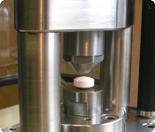
Compression Testing:
Compression testing is carried out using the standard platens supplied with the CT6, as shown here on the right. The machine can be automatically set for the specimen size and the test routine is completely automatic, optionally including weight and thickness measurement.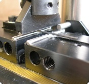
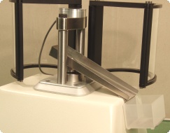
3 & 4 Point Bend Testing:
A 3-point bend rig and 4-point test adapter are available as optional extras.The picture on the right shows a specimen being tested in a 3 point bend rig using 2 mm diameter non-roller lower contact points. These allow very small specimens, down to 8mm long, to be tested.
8 mm diameter roller or non-roller contacts are also available for testing larger specimens. An upper two point roller contact adapter provides the facility for 4 point bend testing.
Click here for more information on 3-point bend testing.
Other Applications:
Engineering Systems can design and manufacture special purpose test rigs and supply various pillar extensions and accessories to special order.| Test | Weight | Thick | Load | |
| No. | (mg) | (mm) | (kg) | |
| 1 | 379 | 4.73 | 1.04 | |
| 2 | 381 | 4.74 | 1.63 | |
| 3 | 380 | 4.74 | 1.82 | |
| LAST RESULT CANCELLED | ||||
| 3 | 378 | 4.71 | 1.43 | |
| 4 | 380 | 4.72 | 1.86 | |
| ---------------------------- | ||||
| BATCH STATISTICS | ||||
| ---------------------------- | ||||
| Batch No: 3 | ||||
| Batch Size: 4 | ||||
| Load Stats | ||||
| ---------------------------- | ||||
| Min: 1.04 kg | ||||
| Max: 1.86 kg | ||||
| Mean: 1.49 kg | ||||
| Std Dev: 0.34 | ||||
| Time: 14:43 FRI 02/05/08 | ||||
| Calibration No: 0004 | ||||
Results Output & Statistical Analysis
After each test is complete the test results are printed on the internal printer (shown opposite) and sent to the USB or RS232 port. If a weigh balance and / or calliper are connected, weight and thickness are also printed.If required the results of the last test can be cancelled; the next test results then replacing those results. In the example here the third result was cancelled.
When a batch is complete statistics can be calculated for load, thickness and weight. Min, Max, Mean & Sample Standard Deviation can be printed for the current batch, along with the batch number & size, and a time / date stamp. Again the statistics are also sent to the USB / RS232 interface.
Each time a new size is set, the product details can be entered using the front-panel keypad. This information will be printed along with the new size details.
Operation
For compression testing, the specimen is placed between the two platens. The bottom platen is stationary, whilst the top platen is attached to a load cell. During a test the load cell moves downwards to crush or break the test specimen. Fracture is automatically detected and the fracture load is displayed on the LCD.The load cell returns to its preset position ready for another test and the internal printer prints the load data, and weight and thickness if a weigh balance and / or calliper are connected. Results can also be displayed on a PC. When testing of the batch is complete, pressing the STATISTICS button gives a print of the statistical data for the batch.
The machine can be used in Manual or Automatic mode:
Automatic mode: A new specimen size is set by pressing the NEW SIZE button, inserting a specimen between the platens and pressing the TEST button. The new size is automatically detected and the machine is ready to test the new batch. The applied load operates at two speeds, test speed and full speed. Test speed is adjustable and can be set between 0.1 and 50 mm/min. Full speed is approx. 50 mm/min. In automatic test mode, the crosshead moves downwards at full speed to within 1 mm of the specimen and the changes to test speed until a fracture or acoustic crack is detected; full reverse speed is then applied and the load cell returns to its preset position.
Manual Mode: The crosshead is positioned using front-panel manual controls and will return by 1 mm after a fracture is detected.
Fracture Detect % Adjustment
During a test, fracture is detected when the instantaneous load falls to a set % of the peak load detected during that test. This is typically set to 70% but can be changed if the tablet or specimen characteristics are unusual. The fracture detect level can be set to any value between 30 and 90%, via the set-up menu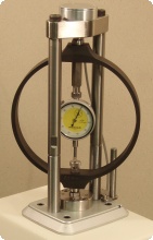
Calibration
Each machine is calibrated before it leaves the factory using a dead weight loading system. The machine can also be re-calibrated using a proving ring, as shown on the right. A daily electronic load check can be made to ensure the calibration is still electronically valid.A passcode protected calibration routine guides users through the calibration procedure and prints a calibration certificate. Previous calibrations can be restored in case a load cell is calibrated accidentally. A calibration number is printed on statistical analysis data to check the correct calibration values are in use.
An optional calibration reminder can be set to warn when re-calibration of a load cell is due. The reminder interval can be set to 6 or 12 months.
Guards
A pair of guards is provided; these rotate about a pivot attached to the load frame base. For batch testing, closing the guards can automatically start the test sequence. If the guards are subsequently opened, the test will be aborted and the crosshead will return to its preset return position.Load Cell ID
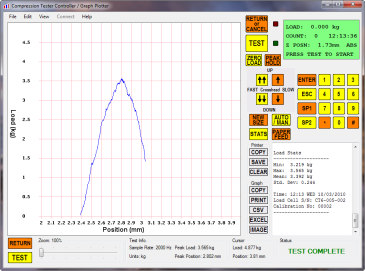
Graph Plotting & Remote Control
During a test, a graph of load vs. crosshead position can be displayed on a PC. The screenshot on the right shows the graph plotter software, which connects to the CT6 via a USB port. Once a test is completed, the graph can examined using the pan and zoom controls, and can be printed. Data can be exported to a CSV file or directly to Microsoft Excel. The graph image can be copied to the clipboard or saved as an image. The software can also be used to remote control the CT6, mimicing it's front panel controls, LCD & printer.A class library is also available to developers wanting to write custom software. This provides the communications interface and raw data processing.
Machine Design & Construction
The CT6 is designed to provide a strong, robust and compact
mechanical strength testing machine which is conservatively
rated on performance. The precision made mechanical loading
system loads the specimen at a constant speed
regardless of applied load. Protection is incorporated to stop a test
cycle if the load cell is overloaded or the crosshead reaches its limit of travel.
Diagnostic messages are shown on the LCD to help resolve any problems that do occur.
The CT6 is housed in a robust steel case, available with a powder coated finish, or optional stainless steel.
The operating firmware in the machine can be updated using a PC via either the
USB or RS232 interface . Customers can check for updated versions of firmware and
find instructions for downloading the firmware here. Specific
customer requirements such as special test or statistics routines or output formats
can be accommodated through custom written firmware - contact Engineering Systems for more details.
Optional Accessories
Accessories available for the CT6 include 500 kg, 50 kg, 10 kg and 5 kg load cells, a waste slide, 3 or 4-point bend rigs, an acoustic sensor and a proving ring. The picture on the right, below, shows the waste slide, used to catch debris after testing, fitted to the CT6. Contact Engineering Systems for more details on any of these.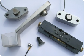
Contact us for up-to-date pricing of the CT6 and accessories.
 TOP OF PAGE
 BACK TO PRODUCTS